Microcontroller based system shutdown, Restart and Logoff using wireless technology
The aim of this project is provide microcontroller-based controlling PC operation such as Shutdown, Restart, and logoff using AT89C51. It consists of RF transmitter-Receiver, Encoder-Decoder pair, AT89C51 and PC. Here the transmission end has a keypad to key in the control code. This control code is given to encoder section to encode it. Here the encoder to encode the data for security. This encoded data is given to RF transmitter for wireless transmission of code. The reception end has a RF receiver to receive the code. This code is given to decoder section. The decoder will recover original code if its address matches with encoder. This decoded signal is given to microcontroller. In microcontroller we have done the program to process the data and to control the corresponding PC operation.

Intelligent home security system using interactive voice Responsive System
This project consists of few pairs of IR trans-receivers placed at various openings such as door, windows and ventilators etc., the microcontroller scans for the interruption of sensors. While a interruption is noticed the microcontroller alerts us with a loud alarm and informs the place of theft by driving a IVR (Interactive voice response unit). A display also indicates the place of disturbance noticed.
Intelligent and automatic Fire security system using interactive voice decoder and telephone Line
ABSTRACT :
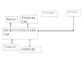
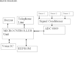
This project-gadget prevents our home/office from the fire accidents. The gadget consists of a temperature sensor, which is to be placed in various positions on the room where there risk of fire. The sensor is LM35, which is a three-pin device. The LM35 converts the temperature data as a voltage data which is a analog data and then the data is given to a comparator segment. The comparator compares with the reference temperature and if the input temperature exceeds the reference value, the comparator triggers the microcontroller. The microcontroller in turn drives a interactive voice decoder and also establishes a phone connection to the police and fire service also the device warns about the dangerous temperature level that may cause fire by a loud alarm.
This project-gadget prevents our home/office from the fire accidents. The gadget consists of a temperature sensor, which is to be placed in various positions on the room where there risk of fire. The sensor is LM35, which is a three-pin device. The LM35 converts the temperature data as a voltage data which is a analog data and then the data is given to a comparator segment. The comparator compares with the reference temperature and if the input temperature exceeds the reference value, the comparator triggers the microcontroller. The microcontroller in turn drives a interactive voice decoder and also establishes a phone connection to the police and fire service also the device warns about the dangerous temperature level that may cause fire by a loud alarm.
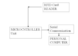
RFID based authentication and device control
Radio frequency identification (RFID) systems use radio frequency to identify, locate and track people, assets, and animals. In this project it consists of active RFID tags,AT89C51 microcontroller unit,RS-232 which is I/O standard cable for serial transmission and MAX 232 for line drivers. Here the information stored in RFID Tags are identified by the RFID module and will be send to microcontroller unit serially via RS-232 cable. Here the tag data is compared with the already stored data in microcontroller by the microcontroller. This output is given to the device which is connected to microcontroller in order to control it.

Auto controlling of 3 phase induction motor
This project can be used with the three phase induction motors. The circuit will take the full control of the motor and it will protect the motor from several faults such us over voltage and under voltage and the circuit will switch on the motor under safety conditions. The circuit was fully controlled by the microcontroller and the microcontroller will continuously monitors the voltages of the three phases and if the voltage goes abnormal then it will switch off the motor until they are normal. All the conditions are displayed it over the LCD display. In our project we are using the popular 8 bit microcontroller AT89C51.It is a 40 pin microcontroller.

Motor parameter monitoring system
ABSTRACT :
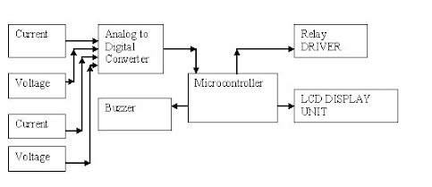
The project is used to measure the parameters such as voltage, Current and speed. The project uses any specified 8 bit microcontroller, the data is measured from the various input sensors and is converted digitally and is fed to microcontroller by means of ADC0804. The microcontroller scans the data input and displays it on the LCD. It also stops the motor whenever the parameters are void, as a prototype model we are using only a small 12v DC motor, for avoiding the risk of shock and other hazards as being a beginner. The project is fully controlled by the 8 bit microcontroller AT 89C51 which has an 8k bytes of ROM for the program memory. The Microcontroller will continuously monitors all the sensors and if it found any problem then the microcontroller will switch on the alarm too.
The project is used to measure the parameters such as voltage, Current and speed. The project uses any specified 8 bit microcontroller, the data is measured from the various input sensors and is converted digitally and is fed to microcontroller by means of ADC0804. The microcontroller scans the data input and displays it on the LCD. It also stops the motor whenever the parameters are void, as a prototype model we are using only a small 12v DC motor, for avoiding the risk of shock and other hazards as being a beginner. The project is fully controlled by the 8 bit microcontroller AT 89C51 which has an 8k bytes of ROM for the program memory. The Microcontroller will continuously monitors all the sensors and if it found any problem then the microcontroller will switch on the alarm too.
RFID based vehicle identification and Speed measurement
ABSTRACT :
The RFID tags are embedded in the vehicles; the sensors are placed at various positions separated at certain distance, so that the speed of the vehicle can be calculated by using the formula Speed = distance/time. These calculations can be done using the microcontroller itself, however we can use the java front – end over the system if one wants to maintain database, else the display can be done in the microcontroller itself for a certain number of vehicles which depends on the memory availability.
The RFID tags are embedded in the vehicles; the sensors are placed at various positions separated at certain distance, so that the speed of the vehicle can be calculated by using the formula Speed = distance/time. These calculations can be done using the microcontroller itself, however we can use the java front – end over the system if one wants to maintain database, else the display can be done in the microcontroller itself for a certain number of vehicles which depends on the memory availability.
PWM based single phase induction motor speed control in closed loop
Abstract :
Cost Of the project : 5000 without motor.
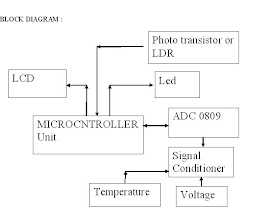
The project is used to control speed of the induction motor using closed loop system .Control of speed is performed using PWM technology. Since, we are going to control a high voltage device; we are isolating the PWM source using opto coupler IC. The motor is driven by TRIAC.By controlling the gating pulses of TRIAC the speed of the motor is controlled. The PWM output is filtered to obtain controlling signals, which is given to gate pin of TRIAC through opto coupler. The speed of the motor is measured using sensor formed by LED and LDR, which give pulses as output according to the speed of the motor. The sensor is connected across the disc, which is connected to the rotor of motor. The pulses from sensor is given as I/P to MC which in turn can determine the speed of the motor, thus the speed of the motor can be maintained that a particular speed.

Image capturing robot for defense
Project Cost :5000/-
Absract :
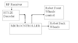
The objective of the project is used to control the robot which has a wireless camera connected in it. The robot helps to monitor an area by a security personal, with out moving from is place. The robot consists of wireless camera, which is capable of capturing live signals and transmit them to a remote location wirelessly. The robot is controlled using RF signals; the RF signals are encoded in order for source communication. The user should guide the robot with the use of the keypad provided to him. The camera connected with the robot continuously scans the image and transmits it wirelessly. The image can be received in the television which is placed few meters away from the camera. The controlling of robot is done with the help of famous ht12d and ht12e decoders – encoder pairs accompanied with RF module. The project is designed with Atmel 89C51 microcontroller.
Absract :
The objective of the project is used to control the robot which has a wireless camera connected in it. The robot helps to monitor an area by a security personal, with out moving from is place. The robot consists of wireless camera, which is capable of capturing live signals and transmit them to a remote location wirelessly. The robot is controlled using RF signals; the RF signals are encoded in order for source communication. The user should guide the robot with the use of the keypad provided to him. The camera connected with the robot continuously scans the image and transmits it wirelessly. The image can be received in the television which is placed few meters away from the camera. The controlling of robot is done with the help of famous ht12d and ht12e decoders – encoder pairs accompanied with RF module. The project is designed with Atmel 89C51 microcontroller.
Image Capturig Robot Transmitter Unit
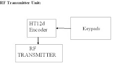
Image Capturing Robot Receiver Unit
******************************************************************************************
**********************************************************
Automatic Electric phase change over
Project Cost :5000/-
Abstract:
The project is much applicable wherever the single phase UN interrupted electrical supply is much essential. Here we just use a three phase line to power a single phase load; the project is much applicable for irrigation pumps in the farming areas. When any one phase of three phases fails it automatically turns the line towards the available phase and powers the irrigation system without interruption. The project uses the opto coupler for sensing the availability of the power supply in the individual phases, and at once if it notes that the power failure in the phase in which load is running presently, it automatically switches the load to the load to the currently available phase using the relay. Thereby ensuring un-interrupted power supply for the specified load.
Working:
The project senses the input voltage via the Optocoupler and in case of power failure automatically Changes to the next phase.
The demo is shown via a small relay connected to the microcontroller.
The single phase driven initially by a phase and then the phase is powered off. Then the microcontroller automatically changes to the nest available power supply.
Note:
The working Model, Classes Kit & complete documentation are available at
Impulse Technologies,
Old no 251 new no 304,
2nd floor arcot road vadapalani Chennai-63.
Contact:
9840103301, 9841091117.

Microcontroller based auto change over switch
ABSTRACT:
This microcontroller based auto change over switch is mainly adopted in industrial and consumer premises where the loads is shared evenly if there is any overload or get failed.
CONTENTS:
The project includes the signal conditional, microcontroller, and change circuit.
The models are:
1) sensing circuit
2) microcontroller unit
3) change over relays
PROPOSED PROJECT:
This project is industrially authorized to change the load from one phase to other phase thus avoiding strain over the central grid.
This project sensing circuit monitors the supply continuously when there is a dip, overload or failure in the supply input. The microcontroller gets the input from sensing circuit and acts as per the conditions. If the supply fails the project initiates the alarm circuit so that the person knows to switch on the generator. The circuit checks for the next line to be switched every time before its changes the supply.
WORKING:
Our project is Automatic Changeover Switch, which automatically changes between the two available supplies. It has three inputs and one output. In some industries there is a need to automatically change between the two available supplies so that the industry can easily share the load and will not cause much strain over the central grid. It automatically changes over to the next available supply in a fraction of second. It the both input supply got failure then the circuit associated with switch produce sound to signal the operator to ON the Generator (i.e. the emergency supply)
The Switch will automatically change the supply at the presetted time. And the circuit every time before switching it checks for the supply at the next line to be switched, It will switch over to the next line only it is live otherwise it maintains the supply with the next line. The main advantage of this switch is that we need not manually change supply every time when any one of the supply got failure. Thus our project will greatly reduce the time consumed in the manual changeover and also reduce the stop in production in the industries. By adopting Micro controller the switching speed will be greatly reduced and the reliability will be improved.
There is also a provision that facilitate the user to enter his own time at which he wants the circuit to switch between the supplies. And the No supply Circuit associated with the switch produces sound when both line got dead thus it alarms the operator to switch ON the Generator (The Third Supply).
ADVANTAGES:
1) Strain in central grid is reduced,
2) Overload in individual phases is eliminated.
3) Indication to switch on the generator.
4) Time consume to manually change over the supply is greatly reduced.
5) Switching speed is very high due to microcontroller.
UPGRADATION:
1) The status of the supply can be displayed to the control room.
2) Automatic generator ON system when supply gets failed.
Reference :
http://www.journal.au.edu/au_techno/2006/july06/vol10no1_a10.pdf